
Preaching to the Converted, Part 2
Principles of Digital Signal Processing.
10 December 2009
Text & Images:/ Scott Willsallen & Luis Miranda
Digital Signal Processing (DSP) is a term you simply can’t avoid as progreessively more systems are moving into the realm of digital audio. So it’s well worth having an understanding of the concepts of signal processing in the digital domain, since they have an audible impact on any sound system.
SIGNALS, SYSTEMS & DSP
In theoretical terms, a signal is the description of how one parameter changes in relationship to another parameter. In analogue audio systems these two parameters are amplitude and time; in digital audio systems the two parameters – as discussed in our previous article [Issue 7] – are discrete amplitude (understood as the quantised amplitude) and, discrete time (the values at each sample point). In basic terms, a system is a process that produces an output signal from an input. DSP in an audio system refers to the process in which an input signal is transformed by a known and predictable way in order to obtain a modified output signal.
Audio systems usually have some basic characteristics which define the way the DSP works. These include:
Time invariance: A time-invariant system is one where the output of the system is independent of time. In a time-invariant system the output of the system will be identical for two identical signals regardless of the time when these signals are input into the system. If a signal is input into the system, the output will be the same if I input the signal now, or two hours later.
Linearity: Linearity is described by two properties:
Homogeneity: This property states that the output of a system is proportional to the input of a system. For example, regardless of the gain applied to a signal, the resulting level will depend on the level of the original signal.
Superposition and additivity: Superposition refers to the property where the response of a system is the same if multiple signals are applied at the same time or separately. Additivity is closely related to this, and states that signals that are added at the input or within the system will produce an output signal that is the addition of the signals. It is important to note that the signals will be added but they will not interact with each other, i.e. they will not create additional frequency content.
These systems are usually known as linear, time-invariant (LTI) systems.

IMPULSE & IMPULSE RESPONSE
We often hear the terms ‘impulse’ and ‘impulse response’ to describe a digital system. In digital audio systems an impulse is a signal where all the sample points have a value of zero except for a single non-zero sample point [see diagram below]. This type of signal is very important in digital systems because it will aid in correctly describing the output of a digital system.
When we input an impulse signal into a digital audio system, the output, also known as impulse response, will have the spectral characteristics of the system… the sonic fingerprint, if you will. We can say that the impulse is the ‘cleanest’ signal available and by using this signal we can measure exactly what a system will do to any signal. It might be obvious, but it’s important to mention that if two systems are different they will have different impulse responses.

CONVOLUTION & RESPONSE OF A SYSTEM
Convolution is the one of the most important operations in digital audio systems. It is a mathematical operation just like addition and multiplication. Whereas addition produces a third number by adding two numbers, convolution produces a third signal by convolving two signals. Generally, in digital audio systems convolution describes how an input signal is transformed by the impulse response of a system and how this operation results in an output signal. The convolution of an input signal with the impulse response of a digital audio system is what dictates the response of the system. When we tailor the impulse response of a system to a desired output we can think of it as a filter.
The result of the convolution is the coming together of the spectral character of the input signal and the spectral character of the impulse response. In practice this operation is done by reversing one of the signals and sliding it across the other signal. The resulting signal will be composed of the sum of the products of the two signals at each position of the process.
This highlights a very important fact of DSP. The resulting signal will be as long as the sum of the sample count of the two signals minus one, as shown in Fig. 2. This longer signal, plus the processing time, is one of the main causes for latency in a system. As complex calculations need to be performed at each position of the convolution, the latency of a system will depend on the length of the filter being used. Longer filters usually have better frequency response, but it is important to know that there is a trade-off between latency and the best achievable frequency response. It is also important to realise that as these filters grow, the usage of computational power also increases.
DSP OPERATIONS & FILTER TYPES
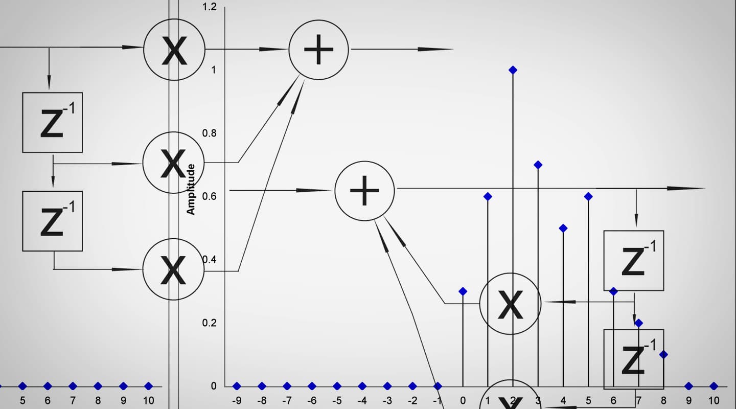
The three most common operators used by digital signal processing devices are: the delay, the adder and the multiplier. These are the three basic pieces used to build filters used by DSP units. Using only these three operators we can build a convolving process.
There are two main types of digital filters: Infinite Impulse Response (IIR) and Finite Impulse Response (FIR). The term FIR filter is used when the output signal in a system is the convolution of the input and the impulse response of the system. In this type of filter the signal moves only in a feed-forward manner. IIR filters are recursive filters; this means that they have a feedback path. The output of the filter will depend not only on the filter but also on the signal applied. Fig. 4 and 5 show diagrams of a second order IIR and a second order FIR. The order of the filter refers to the number of delays accompanied by a multiplier or coefficient.
There are many differences between these two filters. FIR filters are always stable while, due to their recursive nature, IIR filters can cause system saturation if they are unstable. This means that the feedback path will make the level of the signal grow until, in theory, infinity. On the other hand, FIR filters can be designed to be phase linear while this cannot be achieved in IIR. Phase linearity is very important in situations where the integrity of the phase relationships between the signals is important, such as in a sample converter filter. IIR filters can be used in situations where this is not critical, such as in reverberation systems. IIR filters can achieve a similar magnitude response with smaller filters, which make IIR filters more efficient. The length of FIR filters also introduces more latency than IIR filters. The two important factors to keep in mind when selecting filters are the frequency and phase response that we are trying to achieve.


PHASE RESPONSE OF DIGITAL FILTERS
In digital filters we will come across three main phase responses:
Minimum phase: These filters have very short delay times and are frequency dependent. They can produce considerable phase distortion. This type of filter is widely used in situations where small delays are preferable, for example, live audio situations.
Maximum phase: These filters have long delay times and are frequency dependent. They can produce considerable phase distortion. This type of filter is rarely used, since it introduces considerable delay and phase distortion.
Linear phase: These filters have delay times that are proportional to the length of the filter. The delay introduced is the same for all frequencies. This kind of filter is used when it is desirable to preserve the phase relationship of the signal’s components. They can be used in many applications but are not very well suited for live applications if the filters are too long.
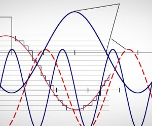


RESPONSES