
Digital Audio Protocols
An introduction to transporting audio over digital networks.
18 April 2010
Text:/ Scott Willsallen & Luis Miranda
Digital audio networks have gained enough ground in the last decade to become the standard means of transport in professional audio. They provide a range of advantages including: being impervious to external noise, ease of connection (one cable where there would typically be many), ease of routing, and no signal degradation over distance or splitting. These advantages do not come without limitations. Some issues associated with digital audio networks that were not present in analogue audio networks include latency, clocking and synchronisation, and lack of standardisation. In this article we’ll look at some of the advantages and issues associated with digital audio networks, together with some network topologies and some of the most common used industry protocols.
DIGITAL AUDIO NETWORK TECHNOLOGIES
Digital audio networks appeared commercially as a natural progression from Digital Signal Processing (DSP) devices. In the previous decade DSP became widely available and affordable through products like the first MediaMatrix Mainframe and the original BSS Soundweb range. If audio was processed digitally, it was only logical to transmit the audio digitally too, especially where multiple locations were part of the system.
Digital audio networks have traditionally been modelled on the available technology for data transmission and thus share similar network topologies and characteristics, so it’s valuable to be familiar with network concepts and terminology when looking at digital audio.
PROTOCOL LAYERS
In the 1970s the International Organization for Standardization (ISO) developed The Open System Interconnection Reference Model (OSI Model) for data communication. This model provides an abstract method for looking at the architecture of any data network. The model views the communication process in functional layers where each layer provides services to the layer above and receives services from the layer below. Because there were seven sub-committees researching this model, it should comes as no surprise to discover that the model has seven functional layers.

Most Ethernet-based audio networks only use the first two layers: Physical and Data Link. The Physical layer describes the electrical and physical specifications for the devices forming the network. The Data Link layer describes the way data will be transmitted in a network, as long as the communication is done node to node within a local area network.
The third (network) layer comes into play when more complicated networks are required. It describes how communications will occur within various networks, and defines addresses for each node, routing through intermediate hosts (routers), sizing packages of data, and maintaining the appropriate Quality of Service (described below). This layer is used for audio delivery in protocols such as Dante where IP is used. This additional layer adds flexibility by allowing the audio data to travel across networks alongside other network traffic.
NETWORK TOPOLOGIES
The network topology describes the way each device in a network is physically connected. The most common network topologies are:

Bus: Each device in the network is connected through a single cable. This topology is rarely used for modern Ethernet connections. USB and IEEE 1394 (Firewire) are virtual bus systems.

Star: Each device is connected to a central hub. Hubs may also be interconnected creating a star of stars topology.

Daisy-chain: Devices are connected in series end-to-end. This is the easiest way to add more devices to a network with the exception of the star topology.

Ring: The same as daisy-chain topology, except the last device is connected to the first device forming a closed loop or ring.

Tree: In this topology there is a central node connected to one or more secondary nodes, which then connect to tertiary nodes and so on. This topology can grow indefinitely, as long as no rings are formed.

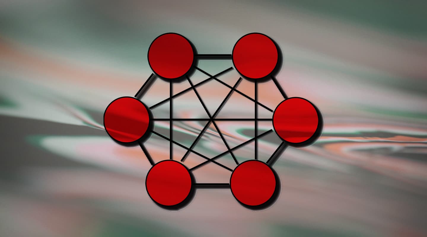
Mesh: This topology allows for all the devices to be connected to any of the devices in the network. More complex routing algorithms are needed in order to avoid data being lost in the mesh connections.
TRANSMISSION SYNCHRONISATION
Transmission synchronization describes the timing with which data is transported into multiple devices. There are two types of transmission synchronisation:
Asynchronous transmission: Asynchronous transmission uses part of the data being transmitted as the synchronisation signal. This scheme is better suited for non-real-time applications.
Synchronous transmission: This technique uses an external source or clock to provide the synchronisation signal. This scheme is used for applications where data needs to be delivered at the same time at different locations, with the lowest amount of latency.
ROUTING SCHEMES
Routing schemes define the way in which a device sends information along the network. The following routing schemes are found in networks:

Unicast: A device sends a message to a single receiver.

Broadcast: A device sends a message to all receivers in the network.

Multicast: A device sends a message to all the devices in a network; the message is then received by the devices that are set to receive the message.

Anycast: A device sends a message to all the devices in a network; the message is then received by the device that is “better” suited to receive the message. This is decided by a set of predefined rules.
QUALITY OF SERVICE (QOS)
QoS is the ability of a network to prioritise packets of data to be transmitted depending on a hierarchy. It will determine the maximum acceptable data rate, latency and the proportion of data errors due to the network. QoS becomes more important as the bandwidth of networks increase and the same network is used for video, audio, and data, because it ensures the activities that require synchronized data with low latency are prioritised in the network.
ADVANTAGES & DISADVANTAGES OF DIGITAL AUDIO NETWORKS
Digital audio networks rely heavily on the advances of data networks. The advantages and disadvantages of digital audio networks are closely linked to the characteristics of the existing data networks technology.
ADVANTAGES
Unlimited signal splitting: Unlike analogue networks where each signal would usually require a separate circuit and an amplifier at each signal split, digital signals can be split and routed to virtually unlimited locations with a simple data network switch. Concerns about signal degradation upon splitting are not an issue either.
Fault tolerance: Through the use of redundant paths and specialised network topologies, digital audio networks can achieve a high degree of fault tolerance. Uninterrupted audio despite faulty network devices is common to many digital audio transport protocols.
Sophisticated network setup and monitoring: It is common for digital audio networks to have a sophisticated network management system that enables such functions as routing and monitoring in complex networks to be handled from a standard computer.
Cabling: Digital audio networks have many cabling advantages over analogue systems. A single digital data cable can carry multiple channels over long distances with little degradation in signal quality. Fewer cables also means fewer failure-prone terminations.
Noise rejection: One of the main problems encountered in analogue audio transport is the introduction of unwanted external noise. Digital audio networks are virtually immune to such problems, even over very long runs.
DISADVANTAGES
Latency: This is one of the biggest issues in digital audio networks. Latency can be introduced in various points along the signal path. To start with, the analogue-to-digital and digital-to-analogue converters add some latency which varies according to the speed of the converter and the bit rate, as a converter needs to perform more approximations at higher bit rates.
Along the network path latency is added at such points as: a) propagation delay, which is the latency added when the information travels through a medium, and is dependent on the type of cable; b) frame delay, which is the result of the time difference between the arrival of the first bit and last bit of an audio word; and, c) switch latency, which is the latency added when the signal encounters a switch along its path. Propagation and switch delay generally have the least impact. The frame delay, the major contributor to latency, varies between manufacturers.
Fault intolerance: Where redundant paths do not exist, failure of one signal path or component means total interruption of the network.
Lack of standardisation: There are many digital audio network formats, and most are not fully compatible even though many of them transport PCM audio. Trying to connect digital audio networks with different protocols can be a titanic, if not impossible, task.


RESPONSES